
Logic gates are essential components in digital electronics, performing basic logical functions based on Boolean algebra. These gates process one or more input signals and generate a single output based on a particular logical rule. Different logic gates are represented by distinct symbols in circuit diagrams, which make understanding their operation much easier. This article will provide a clear explanation of the symbols used for the most common logic gates and their corresponding operations.
Summary of Logic Gates Symbols
Below image shows the summary all basic logic gate symbols.
| Logic Gates Symbols | |||
| Gate | Symbol | Operator | Truth Table |
| AND |  | 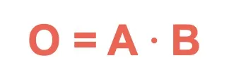 |  |
| OR |  | 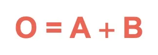 |  |
| NOT |  |  | 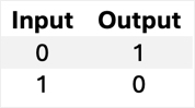 |
| NAND |  | 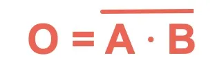 |  |
| NOR |  | 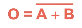 | 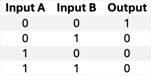 |
| XOR |  | 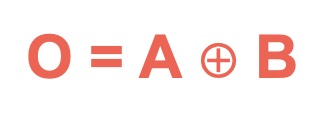 |  |
| XNOR |  | 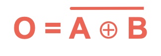 |  |
| Buffer |  |  |  |
| www.webnots.com | |||
1. AND Gate Symbol
The AND gate is one of the simplest logic gates and operates on the principle that the output is true only when all the inputs are true.
Symbol:
The AND gate symbol resembles a flat-ended D shape with two or more input lines on the left and one output line on the right.
Truth Table:
The output is 1 (true) only if all inputs are 1. Otherwise, the output is 0 (false).
| Input A | Input B | Output |
|---|---|---|
| 0 | 0 | 0 |
| 0 | 1 | 0 |
| 1 | 0 | 0 |
| 1 | 1 | 1 |
2. OR Gate Symbol
The OR gate outputs true when at least one of the inputs is true. It outputs false only when all inputs are false.
Symbol:
The OR gate symbol looks like a curved shape, narrowing toward the output with inputs coming from the left.
Truth Table:
If one or more inputs are 1, the output will be 1. The output is 0 only when all inputs are 0.
| Input A | Input B | Output |
|---|---|---|
| 0 | 0 | 0 |
| 0 | 1 | 1 |
| 1 | 0 | 1 |
| 1 | 1 | 1 |
3. NOT Gate Symbol
The NOT gate, also known as an inverter, has only one input and one output. It inverts the input signal, meaning that if the input is 1, the output will be 0 and vice versa.
Symbol:
The NOT gate symbol is a triangle pointing to the right with a small circle (representing inversion) at the output.
Truth Table:
The NOT gate simply reverses the input. A 1 input gives a 0 output, and a 0 input gives a 1 output.
| Input | Output |
|---|---|
| 0 | 1 |
| 1 | 0 |
4. NAND Gate Symbol
The NAND gate is a combination of the AND gate and the NOT gate. It produces the opposite result of an AND gate. The output is true unless all inputs are true.
Symbol:
The NAND gate symbol is similar to the AND gate symbol, but with a small circle (denoting inversion) at the output.
Truth Table:
The output is 1 for all input combinations except when all inputs are 1.
| Input A | Input B | Output |
|---|---|---|
| 0 | 0 | 1 |
| 0 | 1 | 1 |
| 1 | 0 | 1 |
| 1 | 1 | 0 |
5. NOR Gate Symbol
The NOR gate is the combination of the OR gate and the NOT gate. It outputs true only when none of the inputs are true.
Symbol:
The NOR gate symbol is the OR gate symbol with a small circle at the output, indicating inversion.
Truth Table:
If any input is 1, the output will be 0. The output is 1 only if all inputs are 0.
| Input A | Input B | Output |
|---|---|---|
| 0 | 0 | 1 |
| 0 | 1 | 0 |
| 1 | 0 | 0 |
| 1 | 1 | 0 |
6. XOR Gate Symbol
The XOR (Exclusive OR) gate outputs true when only one of the inputs is true. If both inputs are the same, the output is false.
Symbol:
The XOR gate symbol is similar to the OR gate symbol, but it has an additional curved line on the input side.
Truth Table:
The XOR gate gives an output of 1 if one, and only one, of the inputs is 1. The output is 0 if both inputs are the same.
| Input A | Input B | Output |
|---|---|---|
| 0 | 0 | 0 |
| 0 | 1 | 1 |
| 1 | 0 | 1 |
| 1 | 1 | 0 |
7. XNOR Gate Symbol
The XNOR (Exclusive NOR) gate is the inverse of the XOR gate. It outputs true when the inputs are the same.
Symbol:
The XNOR gate symbol is like the XOR gate symbol but with a small circle at the output, indicating inversion.
Truth Table:
The XNOR gate produces a 1 output when both inputs are the same (either both 1 or both 0), and a 0 when the inputs are different.
| Input A | Input B | Output |
|---|---|---|
| 0 | 0 | 1 |
| 0 | 1 | 0 |
| 1 | 0 | 0 |
| 1 | 1 | 1 |
8. Buffer Logic Gate
A buffer is a digital circuit component that outputs the same signal as its input but typically with increased strength or improved signal quality. It is considered a basic type of logic gate, although it does not perform any logical operation (like AND, OR, NOT).
Symbol:
The Buffer symbol is a simple triangle with an input and an output, showing the direct connection of the input to the output without any modifications.
Truth Table:
The Buffer logic gate produces an output that matches the input. If the input is 0, the output is 0. If the input is 1, the output is 1.
| Input | Output |
|---|---|
| 0 | 0 |
| 1 | 1 |
Download Image and PDF
You can download the image for offline reference or download it in a PDF format.

Conclusion
Understanding the symbols and operations of logic gates is fundamental for anyone working with digital electronics or computer engineering. These gates form the basis of digital circuits, enabling more complex operations to be performed when combined. With the knowledge of these gate symbols and their logic, you can begin to interpret and design basic digital circuits effectively.


